
TM 5-1940-322-24
0046 00
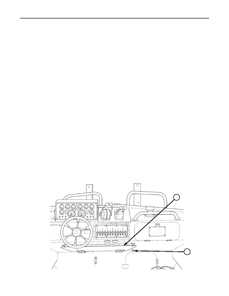
BUS BARS AND JUNCTION BOX REPLACEMENT (Contd)
NOTE
Tag all electrical leads during removal to assist with installation.
BUS BARS REMOVAL
1.
Remove two wing nuts (2) and open access panel (1).
2.
Remove nut (4), lockwasher (28), and electrical leads Nos. 67 (5) and 24 (6) from stud (7) on bus
bar (8). Discard lockwasher (28).
3.
Remove two screws (27), lockwashers (12), and electrical leads Nos. 34F (10) and 34E (11) from bus
bar (8). Discard lockwashers (12).
NOTE
The mounting hardware is the same for both bus bars. Only one
bus bar is shown removed from access panel.
4.
Remove two locknuts (9), washers (19), screws (20), and bus bar (8) from access panel (1). Discard
locknuts (9).
5.
Remove nut (21), lockwasher (18), and electrical leads Nos. 21A (15) and 21B (16) from stud (13) on
bus bar (14). Discard lockwasher (18).
6.
Remove three screws (23), lockwashers (22), and electrical leads Nos. 31B (17), 32B (24), 33B (25),
and 68 (26) from bus bar (14). Discard lockwashers (22).
7.
Remove two locknuts (9), washers (19), screws (20), and bus bar (14) from access panel (1). Discard
locknuts (9).
JUNCTION BOX REMOVAL
NOTE
Tag all electrical leads, cables, and harnesses at removal to assist
in installation.
1.
Loosen four captive screws (31) and remove junction box cover (29), and cover seal (32) from junction
box housing (3). Discard cover seal (32) if damaged.
2.
Remove four captive screws (31) and O-rings (30) from cover (29) if O-rings (30) are damaged.
1
2
0046 00-2

