
TM 5-5420-202-20-1
SYSTEMS OPERATION - Continued
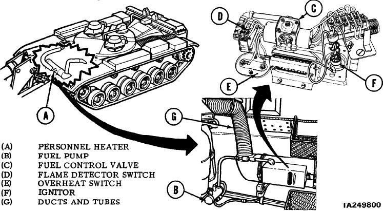
P r o v i d e s heater air for vehicle crew. Circulates air
PERSONNEL HEATER SYSTEM.
t h r o u g h vehicle in air duct system. Air flow speed is constant. Heater switch has two
heater selections, low and high.
(A) PERSONNEL HEATER. Combustion type heater, burns same fuels as engine in a sealed
heat exchanger. Combustion air and air to be heated supplied by two separate blowers on a
single blower motor. Combustion air fan flows air into primary and secondary combustion
air openings where air flows around circular channel in combustion chamber. Combustion
products are exhausted to outside through flexible metal hose coupled through hull to metal
exhaust tube mounted on right front fender.
(B)
FUEL SYSTEM. Fuel flows from personnel heater fuel pump forward of driver's station
to heater where fuel flow is regulated by solenoid-actuated fuel control valve on top of
heater case. Fuel control valve is controlled by personnel heater switch on master
control panel.
Fuel enters through two standpipes on heater and is ignited in
(C) IGNITION CONTROL.
combustion chamber by glow-plug-type ignitor. Electric heating element in fuel control
valve preheats fuel for cold weather starts.
(D) FLAME DETECTOR SWITCH. Shuts off heater motor after flame in heater is established
and permits blower to operate.
S a f e t y switch to shut o f f fuel flow when heater temperature
OVERHEAT SWITCH.
(E)
exceeds safe maximum limits.
(F) IGNITOR. A glow-plug-type ignitor, ignites fuel in combustion chamber.
(G) DUCTS AND TUBES. Ventilating air blower forces air through slots in heat exchanger and
circulates air through a duct and transition box assembly.
2-31

