
TM 5-5420-202-34
ACCELERATOR CONTROL LINKAGE ASSEMBLY REPAIR (Sheet 7 of 13)
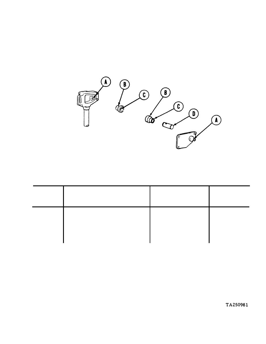
7.
Check linkage assembly components for wear as specified in the following tables. Re-
place all components which do not meet wear limits. Bearings may be removed using
hammer and drift pin or puller. Use vise to install new bearings.
ACCELERATOR LINKAGE WEAR LIMITS
Point of
Reference
Size and fit
Wear
Letter
Measurement
Limits
of New Parts
in.
in.
A
ID of bore in cover & housing
0.875 to 0.876
N/A
B
OD of bearings
N/A
0.876 to 0.878
*
A-B
Fit of bearing in cover & housing
0.000 to 0.003T
C
ID of bearings
0.626 to 0.627
0.632
*
D
OD of shaft
0.618 to 0.620
C-D
Fit of shaft in bearings
0.006L to 0.009L
0.014L
An asterisk (*) in the wear limits column indicates part should be replaced when
worn beyond limits given in size and fit of new parts column.
An L following a dimension indicates loose fit.
A T following a dimension indicates a tight fit.
Go on to Sheet 8

