
TM 5-5420-202-34
TRACK ADJUSTING LINK REPAIR (Sheet 5 of 13)
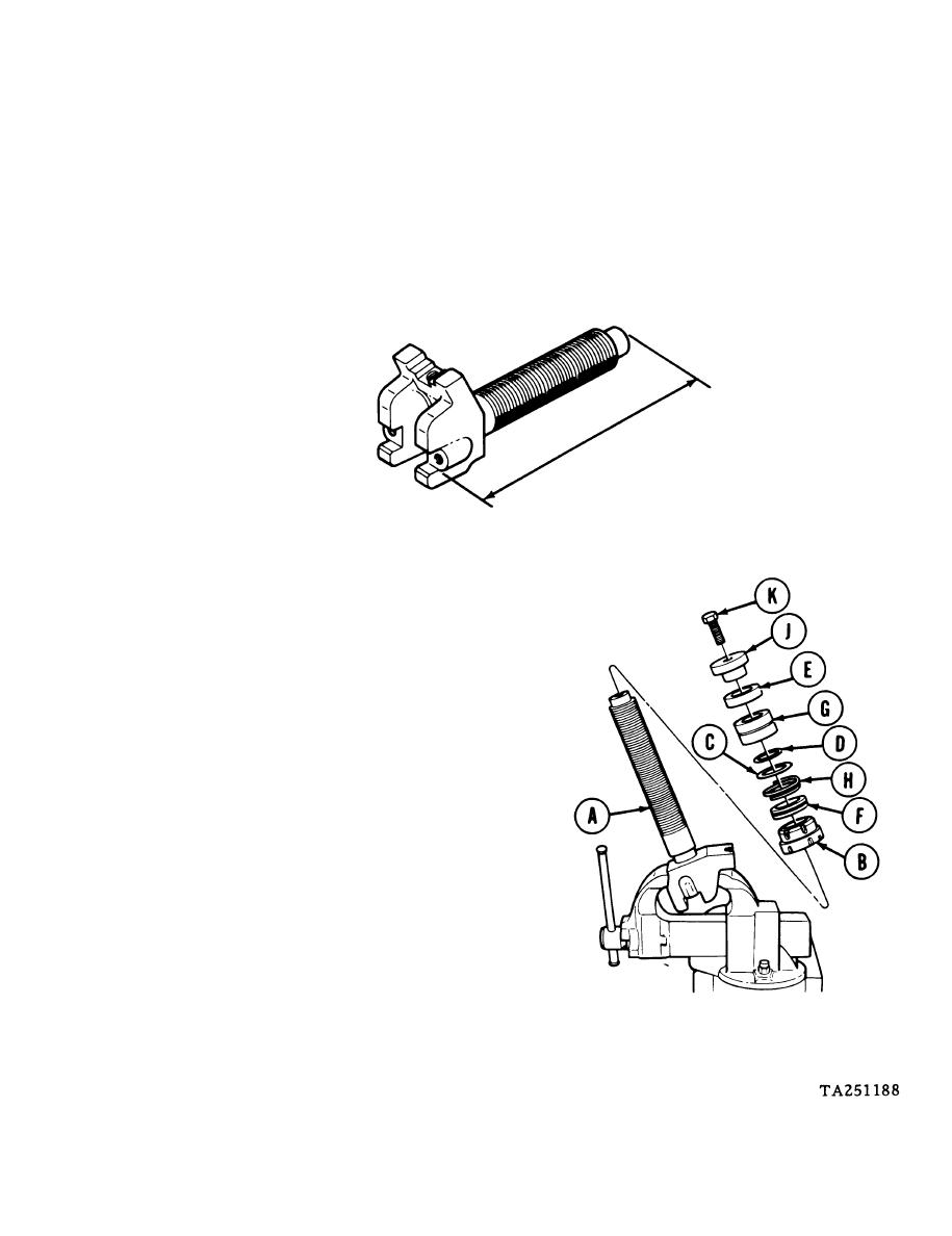
ASSEMBLY:
NOTE
Shafts are not interchangeable. Right side adjusting link
shaft is approximately 16 5/8 inches long and left side is
approximately 13 3/8 inches long. Measure shaft as shown
to distinguish right side from left.
Put shaft (A) in vise.
1.
Apply a light coat of grease to threads
2.
of shaft (A), nut (B), new packings
(C and D), and cup (E).
Install nut (B) and support (F) on shaft
3.
(A).
Install new packing (D) inside piston (G).
4.
Install new packing (C) and retainer (H)
5.
in groove on piston (G).
Put piston (G), cup (E), and follower (J)
6.
on shaft (A).
Apply a coat of sealing compound to
7.
threads of screw (K) with brush.
Using 15/16 inch socket, install screw
8.
(K) and tighten to end of shaft (A).
Torque screw (K) to 90-110 lb-ft (122-
9.
149 Nm).
Remove assembled shaft (A) from vise.
10.
Go on to Sheet 6
9-33

