
TM 5-5420-202-34
STEERING SHAFT ASSEMBLY REPAIR AND REPLACEMENT (Sheet 2 of 3)
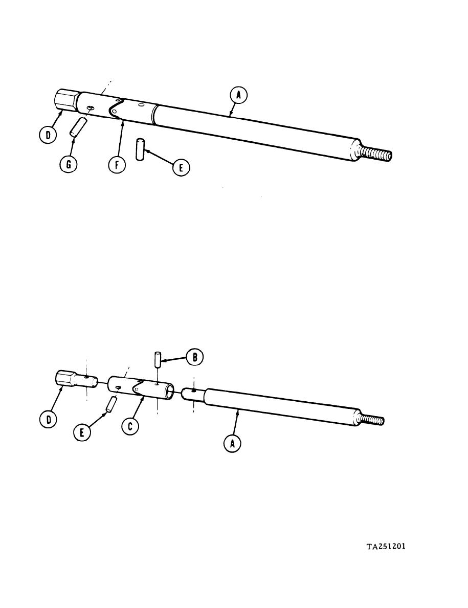
3.
Position shaft (A) in vise and using hammer and punch, remove pin (E) from universal
joint (F). Throw pin (E) away.
4.
Using hammer and punch, remove pin (G) from universal joint (F). Throw pin (G) away.
5.
Remove plug (D) from universal joint (F).
6.
Remove shaft (A) from universal joint (F).
7.
Inspect shaft (A), universal joint (F), and plug (D) for looseness and wear. Replace de-
fective parts.
INSTALLATION:
1.
Position shaft (A) in vise and, using hammer and punch, install new pin (B) into universal
joint (C) and shaft (A).
2.
Position plug (D) into universal joint (C) and using hammer and punch, install pin (E) into
universal joint (C) and plug (D).
Go on to Sheet 3
10-8

