
TM 5-5420-226-20-3
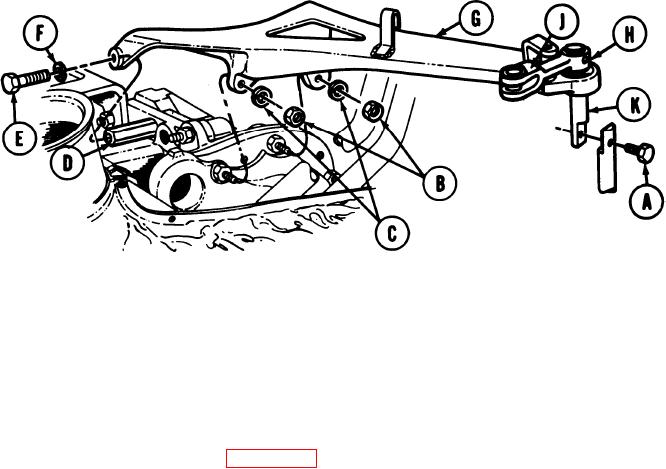
SHIFTING CONTROL BRACKET ASSEMBLY AND CONNECTING LINK
REPLACEMENT (Sheet 2 of 2)
3.
Using 3/4 inch wrench to hold stud (D), use 3/4 inch wrench to remove screw (E) and
lockwasher (F).
4.
Remove bracket assembly (G) from transmission.
5.
Using punch and hammer, remove spring pin (H). Throw pin away.
6.
Remove lever (J).
7.
Remove shaft (K).
INSTALLATION:
1.
Install shaft (K) in bracket assembly (G).
Position lever (J) on shaft (K).
2.
Using hammer, install new spring pin (H) through lever (J) and shaft (K).
3.
Position bracket assembly (G) on transmission.
4.
Using 3/4 inch socket with extension, install two nuts (B) and lockwashers (C).
5.
Using 3/4 inch wrench, install screw (E) and lockwasher (F).
6.
Using 7/16 inch wrench, install screw (A) through both parts of connecting link (K).
7.
Install shifting control lever (page 11-37).
8.
End of Task
TA169041

