
TM 5-5420-226-20-3
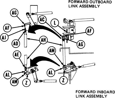
SHIFT LINKAGE ADJUSTMENT (Sheet 11 of 28)
49.
Using 9/1 6 inch wrench, adjust shifting rod
bearing end (AG) clockwise until shifting
rod (AH) is past hole (AJ).
Using 9/16 inch wrench, remove screw (AM).
50.
Using 9/16 inch wrench, install screw (AF)
51.
through clevis (AC) and shifting rod bearing
end (AG).
Holding rod bearing end (AL) with 9/1 6 inch
52.
wrench, use torque wrench and 9/1 6 inch
crow foot adapter to tighten jamnut (AD) to
16-18 lb-ft (22-24 Nm).
53.
Using torque wrench and 9/1 6 inch socket,
tighten screw (AF) to 16-18 lb-ft (22-24 Nm).
54.
Using 9/16 inch wrench, adjust shifting rod bearing end (AL) by turning clockwise or
counterclockwise until screw (AM) will drop freely through clevis (Z) and shifting rod
bearing end (AL).
55.
Using 9/16 inch wrench, install screw (AM).
56.
Holding rod bearing end (AL) with 9/16 inch wrench, use torque wrench and 9/16 inch
crow foot adapter to tighten jamnut (AE) to 16-18 lb-ft (22-24 Nm) and remove locating
pin (L).
57.
Using torque wrench and 9/16 inch socket, tighten screw (AM) to 16-18 lb-ft (22-24 Nm)
and go on to step 68.
Go on to Sheet 12
TA169064
11-63

