
TM 5-5420 -226-20-3
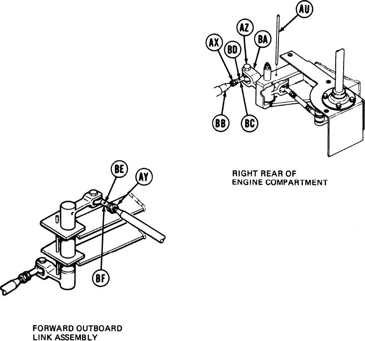
SHIFT LINKAGE ADJUSTMENT (Sheet 15 of 28)
NOTE
Do not allow shifting rod (BB) to turn while doing
step 77. Shifting rod (BB) is made up of more than
one piece and may come apart if allowed to turn.
77.
Using 9/16 inch wrench, adjust shifting rod
bearing end (BC) by turning clockwise or
counterclockwise until screw (AZ) will drop
freely through clevis (BA) and shifting rod
bearing end (BC).
78.
Using small diameter wire, check to see if
shifting rod (BB) is past holes (BD) and
(BE). If shifting rod (BB) is past holes
(BD) and (BE), do steps 79 thru 81. If
shifting rod (BB) is not past hole (BD), do
steps 82 thru 91. If shifting rod (BB) is
not past hole (BE), go on to step 92.
79.
Using 9/16 inch wrench, install screw (AZ).
Holding rod bearing ends (BC) and (BF) with 9/16 inch wrench, use torque wrench and
80.
9/16 inch crow foot adapter to tighten jamnuts (AX) and (AY) to 16-18 lb-ft (22-24 NZm)
and remove locating pin (AU) from alinement holes.
81.
Using torque wrench and 9/16 inch socket, tighten screw (AZ) to 16-18 lb-ft (22-24 Nm)
and go to step 102.
Go on to Sheet 16
TA169068
11-67

