
TM 5-5420-226-20-3
SHIFT LINKAGE ADJUSTMENT (Sheet 27 of 28)
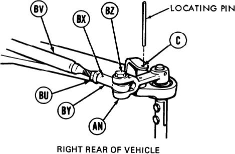
141.
Using 9/16 inch wrench, adjust shifting
rod bearing end (BY) by turning clockwise
or counterclockwise until screw (BZ) will
drop freely through clevis (AN) and shifting
rod bearing end (BY).
142.
Using 9/16 inch wrench, install screw (BZ)
through clevis (AN) and shifting rod bearing
end (BY).
143.
Holding rod bearing end (BY) with 9/16 inch wrench, use torque wrench and 9/16 inch
crow foot adapter to tighten jamnut (BU) to 16-18 lb-ft (22-24 Nm).
144.
Remove locating pin from alinement hole (C).
145.
Using torque wrench and 9/16 inch socket, tighten screw (BZ) to 16-18 lb-ft (22-24 Nm)
and go to step 156.
146.
Using 9/1 6 inch wrench, remove screw (BZ) and remove shifting rod bearing end (BY) from
clevis (AN).
147.
Using 9/16 inch wrench, adjust shifting rod bearing end (BY) by turning clockwise until
shifting rod (BV) is past hole (BX).
148.
Using 9/16 inch wrench, install screw (BZ) through clevis (AN) and shifting rod bearing end
(BY).
149.
Holding rod bearing end (BY) with 9/16 inch wrench, use torque wrench and 9/16 inch
crow foot adapter to tighten jamnut (BU) to 16-18 lb-st (22-24 Nm).
150.
Using torque wrench and 9/16 inch socket, tighten screw (BZ) to 16-18 lb-ft (22-24 Nm).
Go on to Sheet 28
TA169080
11-79

