
TM 5-5420-226-20-3
BRAKES ADJUSTMENT (Sheet 2 of 8)
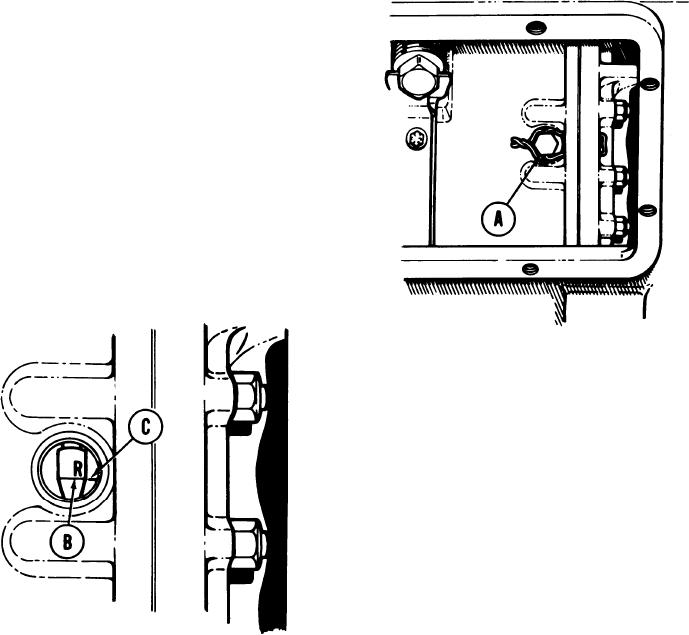
NOTE
Both right and Ieft brakes must be adjusted. Left brake
adjustment is located equally opposite right brake
adjustment on transmission.
1.
Using pliers, cut two locking wires holding
two brake inspection hole plugs (A).
Remove locking wires.
2.
Using 7/8 inch wrench, remove two
brake inspection hole plugs and gaskets
(A).
Check whether index line (B) marked
3.
R and index mark (C) are lined up.
Go on to Sheet 3
TA169203
13-79

