
TM 5-5420-226-20-3
BRAKES ADJUSTMENT (Sheet 5 of 8)
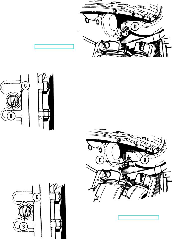
Using 1 inch wrench, install brake adjusting
9.
worm cap (D).
Fully apply brakes (TM 5-5420-226-10).
10.
Check whether index line (B) marked
11.
A and index mark (C) are lined up.
If index line (B) marked A and index
12.
mark (C) are lined up within 1/64 inch,
brakes are adjusted. Release brakes
and go to step 24.
If index line (B) marked A and index
13.
mark (C) are not lined up within 1/64
inch, release brakes and go to step 14.
Using 1 inch wrench, remove brake adjusting
14.
worm cap (D).
Using 15/16 inch wrench, loosen locknut
15.
(E).
16.
Fully apply brakes (TM 5-5420-226-10).
If index line (B) marked A moves past
index mark (C), brake is too loose.
TA169206
Go on to Sheet 6
13-82

