
TM 5-5420-226-20-3
BRAKES ADJUSTMENT (Sheet 6 of 8)
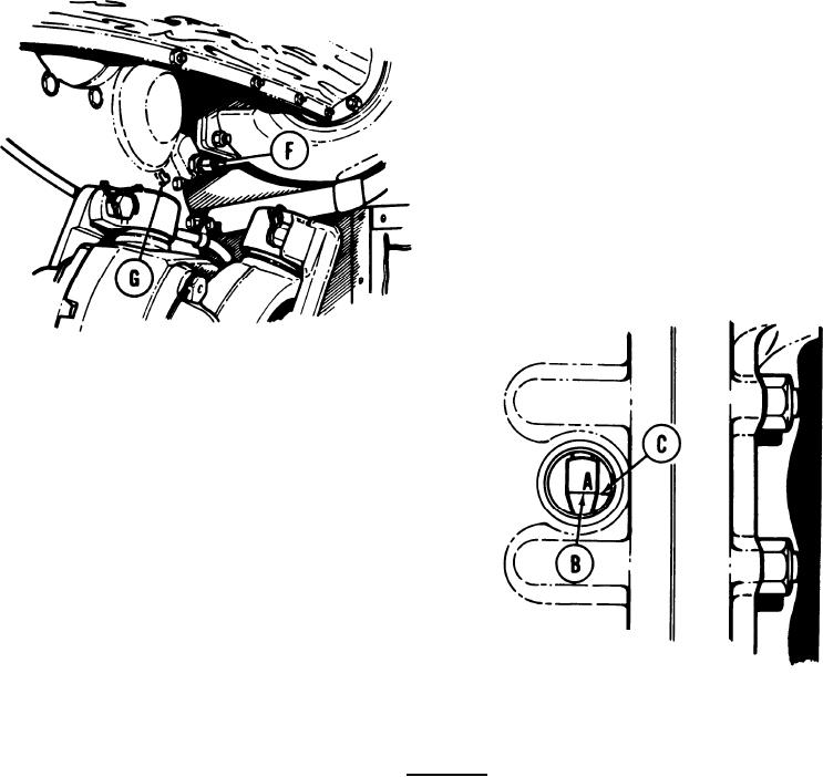
17. Release brakes.
18.
Using 7/16 inch wrench, turn brake
adjusting worm (F) in direction of arrow
(G) on transmission end cover (right
side, turn counterclockwise; left
side, turn clockwise).
If index line (B) marked A does not move
19.
back to index mark (C), brake is too
tight.
Using 7/16 inch wrench, turn brake
20.
adjusting worm (F) about 25 turns toward
opposite direction of arrow (G) on trans-
mission end cover (right side, turn
clockwise; left side, turn counterclock-
wise).
NOTE
Always try to bring index line (B) marked A, and index
mark (C) into line by turning brake adjusting worm (F)
counterclockwise.
CAUTION
Always release brakes before making adjustments.
21.
Using 7/16 inch wrench, turn brake adjusting worm (F) in direction of arrow (G) until
index line (B) marked A, lines up with index mark (C) when brakes are applied.
TA169207
Go on to Sheet 7
13-83

