
TM 5-5420-226-20-3
PARKING BRAKE CONTROL ASSEMBLY AND LINKAGE REPLACEMENT (Sheet 3 of 17)
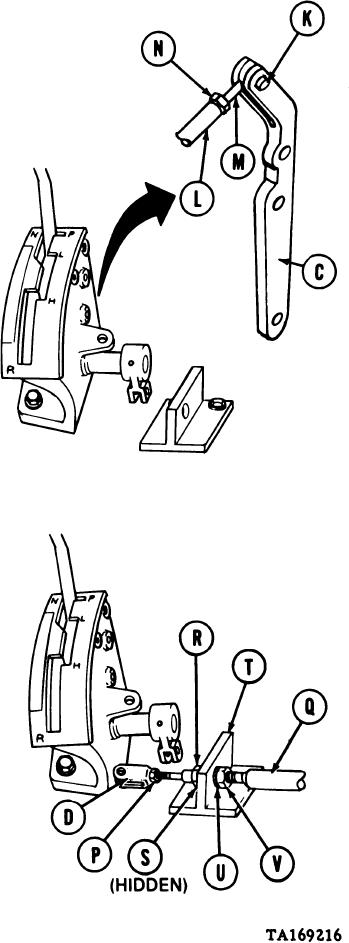
4.
Remove lever (C), spring pin (K), straight
pin (L), rod end connector (M), and nut
(N) as a unit.
5.
Using 7/16 inch wrench, hold nut (N),
use pliers and remove straight pin (L)
from rod end connector (M).
6.
Using 7/16 inch wrench, remove nut
(N) from rod end connector (M).
7.
Using hammer and punch, drive out
spring pin (K) from lever (C). Throw
spring pin (K) away.
Using 9/16 inch wrench, hold nut (P),
8.
use 8 inch adjustable wrench to remove
clevis (D) from control assembly (Q).
Using 9/16 inch wrench, remove nut
9.
(P) from control assembly (Q).
10.
Using 15/16 inch wrench, remove nut
(R) and lockwasher (S) from control
assembly (Q).
11.
Pull control assembly (Q) through support
bracket (T).
Using 15/16 inch wrench, remove lock-
12.
washer (U) and nut (V) from control
assembly (Q).
Go on to Sheet 4
13-92

