
TM 5-5420-226-20-3
PARKING BRAKE CABLE ADJUSTMENT (Sheet 3 of 4)
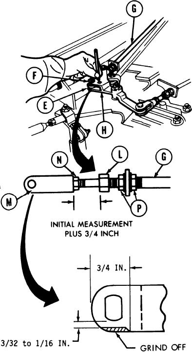
7.
Using ruler, measure distance between
nut (L) and connector (M) after brake
cable (G) is pushed inward as far as
possible. Record reading.
8.
Pull brake cable (G) outward 3/4 inch
farther than reading taken in step 7.
NOTE
Do not change 3/4 inch
position when performing steps
9 and 10.
Position connector (M) in bellcrank (H).
9.
Insert pin (F) and clip (E). Using torque
wrench and 9/16 crow foot wrench, tighten
jamnut (N) to 28-30 lb-ft (38-41) Nm).
Do not allow cable (G) to turn or damage
will result. Nuts and clevises must thread
freely on cables (step 10).
10. If pin cannot be freely inserted in connector
(M), using 15/16 inch wrench, loosen
two nuts (P) and adjust cable travel
maintaining distance in step 8 until
connector (M) and bellcrank (H) will
aline. Tighten two nuts (P) after inserting
pin and clip. Tighten nuts (P) to 45-
50 lb-ft (61-68 N m).
NOTE
An interference may exist between clevis and locating
pin during this adjustment procedure. It may be
necessary to grind clevis as shown to eliminate this
TA169252
Go on to Sheet 4
13-128

