
TM 5-5420-226-20-3
STEERING CONTROL LINKAGE ADJUSTMENT (Sheet 14 of 22)
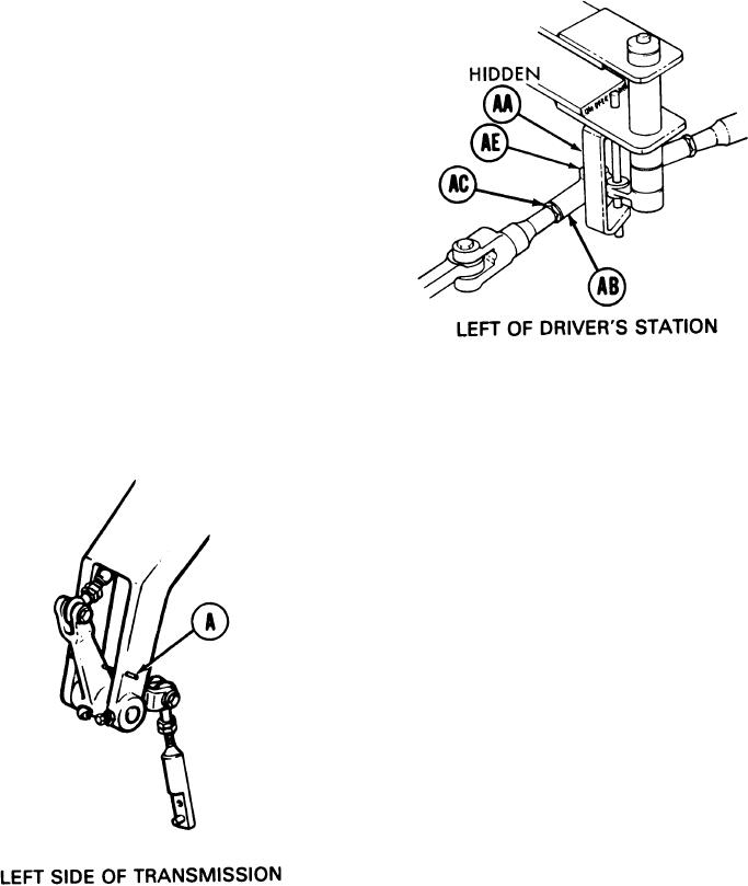
Using 9/16 inch wrench, turn steering rod
71.
end (AB) counterclockwise until screw
(AA) will drop freely through clevis (AE)
and steering rod end (AB).
Using 9/16 inch wrench, install screw
72.
(AA).
Using torque wrench and crowfoot, tight-
73.
en screw (AA) to 16 lb-ft (22 Nm).
74. Using 9/16 inch wrench to hold steering rod end (AB), use 9/16 inch wrench to tighten
jamnut (AC).
NOTE
Do not remove Iocater pins already
installed.
Try to insert locating pin (A). If locating
75.
pin (A) can be inserted, linkage is in adjust-
ment. Go on to step 128. If locating pin
(A) cannot be inserted remove powerplant
(page 5-2) and go on to step 76.
TA169404
Go on to Sheet 15
15-44

