
TM 5-5420-226-20-3
STEERING CONTROL LINKAGE ADJUSTMENT (Sheet 15 of 22)
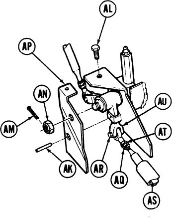
76.
Try to insert locating pin (AK). If locating
pin (AK) can be inserted, go on to step
109. If locating pin (AK) cannot be inserted
go to step 77.
Using 7/16 inch wrench, remove screw
77.
(AL).
78.
Using pliers, remove cotter pin (AM).
Throw cotter pin (AM) away.
79.
Using 3/4 inch wrench, remove nut (AN)
and remove plate (AP).
Using 9/16 inch wrench, loosen jamnut (AQ).
80.
81.
Using 9/16 inch wrench, remove screw (AR).
82.
Move link assembly and insert locating pin (AK).
Using 9/16 inch wrench, adjust length of control rod (AS) by turning steering rod end
83.
(AT) clockwise or counterclockwise until screw (AR) can be freely inserted through clevis
(AU) and steering rod end (AT).
Go on to Sheet 16
TA169405
15-45

