
TM 5-5420-226-20-3
NO. 1 AND NO. 2 OUTRIGGER REPLACEMENT (Sheet 3 of 3)
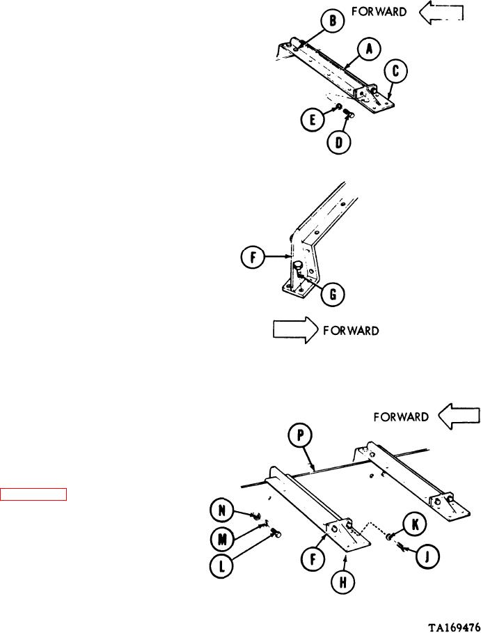
INSTALLATION:
1.
Place outrigger (A) imposition.
2.
Using 13/16 inch socket, extension, and
ratchet, install four screws (B).
Place end plate (C) imposition.
3.
Using 9/16 inch socket, install two screws
4.
(D) and lockwashers (E).
5.
Place outrigger (F) in position.
6.
Using 13/16 inch socket, extension, and
ratchet, install four screws (G).
Place end plate (H) in position to join out-
7.
rigger (F).
Using 9/16 inch socket, install two screws
8.
(J) and lockwashers (K).
Using 9/16 inch socket, install four screws
9.
(L), lockwashers (M), and washers (N) to
secure shroud (P) to outrigger (F).
10.
Install fender plates No. 1, No. 2 and No.
3 (pages 16-47, 16-52, and 16-54).
End of Task
16-64

