
TM 5-542-226-20-3
REAR FENDER STOWAGE BOX AND FENDER REPLACEMENT AND REPAIR (Sheet 1 of 9)
PROCEDURE INDEX
PROCEDURE
PAGE
Removal
Repair
Installation
TOOLS: 9/16 in. combination box and open end wrench (two required)
3/4 in. combination box and open end wrench (two required)
3/8 in. combination box and open end wrench
Pliers, slip joint
9/16 in. socket with 1/2 in. drive
Ratchet with 1/2 in. drive
SUPPLIES:
Locknuts (MS-51988-7) (36 required)
Locknut (MS-51988-11) (3 required)
Cotter pins (2 required)
NOTE
Removal and installation procedure is
the same for both left and right sides.
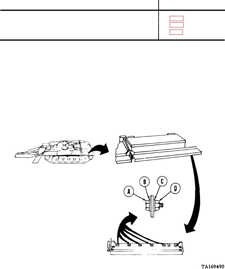
REMOVAL
1.
Using 9/16 inch wrench and 9/16 inch
socket, remove five screws (A), plates (B),
washers (C), and locknuts (D). Throw
locknuts away.
Go to Sheet 2

