
TM 5-5420-227-24
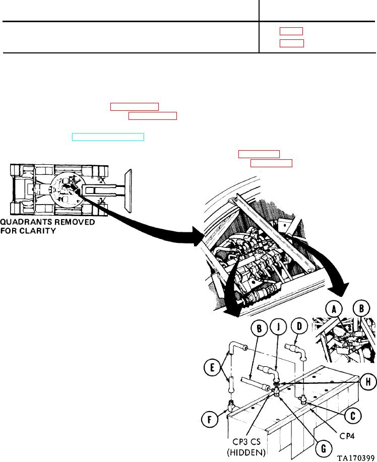
LOCKING CYLINDER HOSE ASSEMBLIES (EA1, CP3, CP4 and CS) AND HYDRAULICS
REPLACEMENT (Sheet 1 of 4)
PROCEDURE INDEX
PROCEDURE
PAGE
Removal
Installation
TOOLS: 12 in. adjustable wrench (2)
15/16 in. open end wrench
1-1/4 in. open end wrench
8 in. pipe wrench
11/16 in. open end wrench
7/8 in. open end wrench
Drip pans
Pencil
SUPPLIES:
Rags (Item 12, Appendix D)
Tags, identification
Pipe tape (Item 19, Appendix D)
Preformed packing (4 required)
REFERENCE:
Remove front quadrant (page 3-39)
PRELIMINARY PROCEDURES:
Relieve hydraulic pressure (page 3-65)
REMOVAL:
NOTE
Use rags and drip pans to catch excess hydrau -
tic fluid. Use tags to identify lines for instal-
lation.
Using adjustable wrench on elbow (A), use
1.
1-1/4 inch wrench to remove hose assembly
"CS" (B).
Using adjustable wrench on tee (C), use
2.
adjustable wrench to disconnect hose
assemblies "CP4" (D) and "EA1" (E).
Using adjustable wrench on elbow (F), use
3.
15/1 6 inch wrench to remove hose assembly
"EA1" (E).
Using adjustable wrench on tee (G), use 1-1/4
4.
inch wrench to remove hose assembly "CS" (B).
5.
Using 1-1/4 inch wrench on nut (H), use
11/16 inch wrench to remove hose assembly
"CP3" (J).
Go on to Sheet 2
3-174

