
TM 5-5420-227-24
CLU T CH ASSEM BLY REPLACEM EN T AN D REPAI R (She e t 7 of 9 )
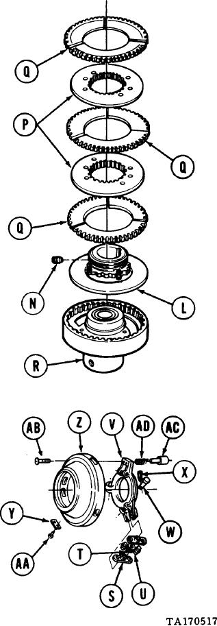
Using 1/4 inch screw key, loosely install
11.
setscrew (N) so it is below thread level
of hub and backplate (L).
Manually install hub and backplate (L),
12.
two clutch discs (P), and three friction
linings (Q) on clutch spider assembly (R)
in order shown.
Assemble six levers (S), three springs (T),
13.
and six pins (U) into three assemblies as
shown.
Place three assemblies in position on yoke
14.
(v).
Install three pins (W) securing three
15.
assemblies to yoke (V).
Using pliers, install three new cotter pins (X)
16.
through pins (W).
Place plate (Y) in position on cover (Z).
17.
Using hammer, tap in two new drive screws
18.
(AA).
Using flat-tip screwdriver, install three
19.
screws (AB) securing cover (Z) to yoke (V).
20.
Place pin (AC) and spring (AD) in position
through yoke (V) and cover (Z).
Manually pull out on pin (AC) and lock in
21.
place by pushing locating pin through
hole in pin (AC).
Go on to Sheet 8
4 -3 9

