
TM 5-5420-228-24
CUPOLA TOP AND VISION BLOCK REPLACEMENT (LATE MODEL CUPOLA) (Sheet 1 of 3)
TOOLS:
Diagonal cutting pliers (side cutters)
Chisel
1-1/8 in. socket with 1/2 in. drive
Hammer
3/4 in. socket with 1/2 in. drive
Ratchet with 1/2 in. drive
Crowbar
1-1/8 in. socket with 3/4 in. drive
Sledge hammer
Pliers, slip joint
Putty knife
Torque wrench 0 to 600 lb-ft 3/4 in. drive
1/2 in. combination wrench
(0 to 813 N.m)
SUPPLIES:
Adhesive (Item 2, Appendix D)
Lockwire (Item 20, Appendix D)
Seal
Brush (Item 4, Appendix D)
PERSONNEL:
Two
REFERENCE: TM 5-5420-202-10
PRELIMINARY
PROCEDURE:
Open cupola
cover (TM 5-5420-202-10)
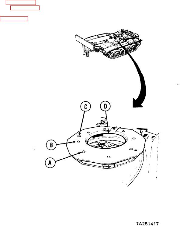
REMOVAL:
Using 1-1/8 inch socket, remove
1.
eight screws (A).
2.
Using 3/4 inch socket, remove
three screws (B).
Using crowbar, pry up on edge of
3.
cupola top (C) while second technician
taps edge of cupola top (C) with
sledge hammer to loosen it.
4.
With help from second technician,
remove cupola top (C) from vehicle.
Using putty knife, remove seal (D).
5.
Go on to Sheet 2

