
TM 5-5420-228-24
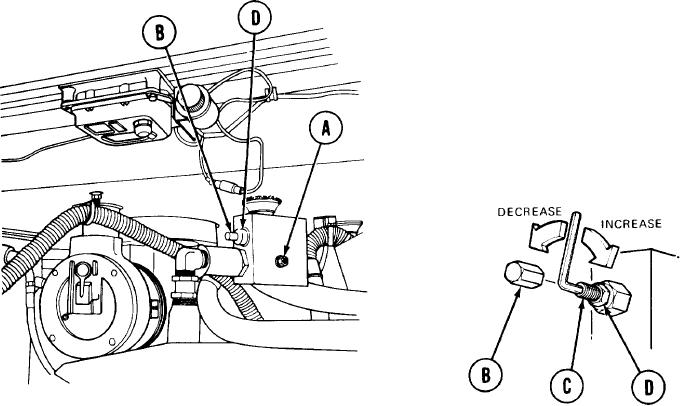
MASTER RELIEF VALVE (RV1) ADJUSTMENT (Sheet 2 of 2)
NOTE
Correct pressure is 3800 50 psi (26220 340 kPa).
Using wrench, remove adjusting screw cap (B).
8.
To adjust relief valve pressure, hold adjusting screw (C) with 3/16 inch screw key and
9.
use wrench to loosen jamnut (D). Using 3/16 inch screw key, turn adjusting screw (C)
clockwise to increase pressure or counterclockwise to decrease pressure.
Repeat steps 3 through 9 until pressure gage shows reading of 380050 Psi (26220
10.
340 kPa).
Holding adjusting screw (C) with 3/16 inch screw key, use wrench to tighten jamnut
11.
(D).
Using wrench, install adjusting screw cap (B).
12.
Remove pressure gage.
13.
Using 1/4 inch screw key, install plug (A).
14.
TA251475
End of Task
3-77

