
TM 5-5420-228-24
SCISSOR CYLINDER RELIEF VALVE (RV8) ADJUSTMENT (Sheet 1 of 1)
TOOLS: 3/16 in. socket head screw key
1/4 in. socket head screw key-
9/16 in. open end wrench
SPECIAL TOOLS: Gage, pressure (item 3, sec III, app B)
Two
PERSONNEL:
REFERENCE:
TM 5-5420-202-10
PR.E
If S
51 (page -2-47)
1.
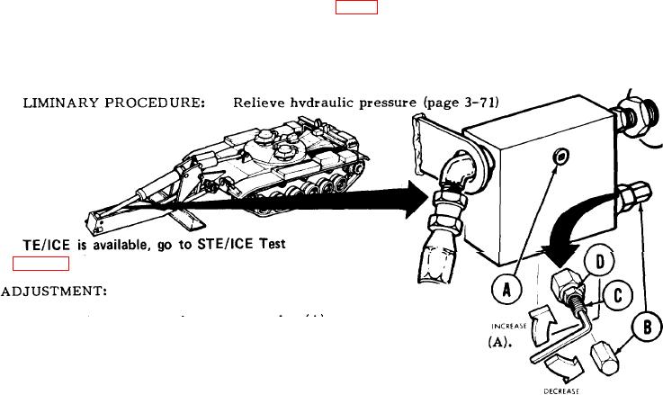
Using 1/4 inch screw key, remove plug (A).
Manually install pressure gage in opening left by removal of plug
2.
Engage hydraulic pump (TM 5-5420-202-10).
3.
Set engine speed at 1800 rpm.
4.
Slowly push up overhead cylinder control lever until outrigger contacts ground' and
5.
hold in that position.
Have second technician observe pressure gage reading.
6.
Return overhead cylinder control lever to neutral position.
7.
Remove adjusting screw cap (B) using wrench.
8.
NOTE
Correct pressure is 3400 50 psi (23443 340 kPa.
To adjust relief valve pressure, hold adjusting screw (C) with 3/16 inch screw key and
9.
use wrench to loosen jamnut (D). Using 3/1 6 inch screw key, turn adjusting screw (C)
clockwise to increase pressure or counterclockwise to decrease pressure.
Repeat steps 3 through 9 until pressure gage shows reading of 3400 50 psi (23443
10.
-- 340 kPa).
+
11.
Holding adjusting screw (C) with 3/16 inch screw key, use wrench to tighten jamnut
(D).
12.
install adjusting screw cap (B) using wrench.
13.
Remove pressure gage.
Using 1/4 inch screw key, install plug (A) and tighten.
14.
TA251487
End of Task

