
TM 5-5420-228-24
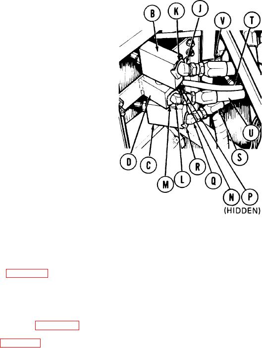
SEQUENCE AND LOCKING CYLINDER RELIEF VALVE (RV5 AND RV6) REPLACEMENT
(Sheet 3 of 3)
6.
Using adjustable wrench, install elbow
(J) and collar "CS" (K) on top relief
valve "RV6" (B).
7.
Using adjustable wrench, install elbow
(L) and collar "CR" (M) on rear of manifold (D).
8.
Using adjustable wrench, install elbow (N) and
collar "AR" (P) on side of manifold (D).
Using adjustable wrench, install elbow (Q) and
9.
collar "CT" (R) on bottom relief valve "RV5" (C).
10.
Using 1-1/4 inch wrench, install hose assembly
"CT" (S) on elbow (Q).
11.
Using 9/16 inch wrench, install hose assembly "AR" (T) on elbow (N).
12.
Using 1-1/4 inch wrench, install hose assembly "CR" (U) on elbow (L).
13.
Using 1-1/4 inch wrench, install hose assembly "C S" (V) on elbow (J).
14.
Bleed hydraulic system (page 3-72).
Check for hydraulic leaks and correct as necessary.
15.
16.
Service hydraulic reservoir (LO 5-5420-202-12).
Adjust pressure in relief valves (pages 3-86 and 3-87).
17.
18.
Install front quadrant (page 3-46).
End of Task
TA251503
3-105

