
TM 5-5420-228-24
H Y DRAU LI C FLU I D FI LT ER ASSEM BLY REPLACEM EN T (She e t 1 of 3 )
TOOLS: 7/16 in. open end wrench
1/4 in. socket head screw key
1-1/2 in. open end wrench
18 in. pipe wrench
15 in. adjustable wrench
Vise
Drip pan (suitable containers)
SUPPLIES:
Rags (It em 12, Appendix D)
Lockwasher
Pipe tape (Item 19, Appendix D)
LO 5-5420-202-12
REFERENCE:
Drain hydraulic reservoir (page 3-74)
PRELIMINARY PROCEDURE:
REMOVAL:
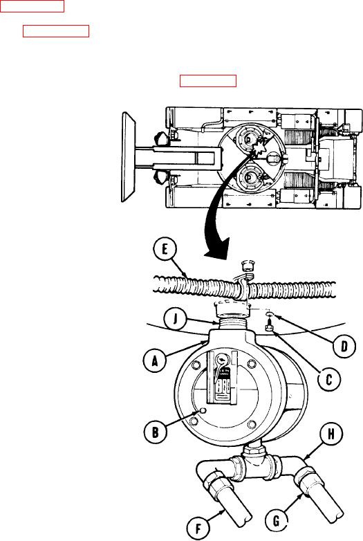
N OT E
U se drip pa n t o c a t c h hydra ulic fluid
t ra ppe d in filt e r a sse m bly (A).
1.
Using 1/4 inch screw key, remove pipe plug
(B).
2.
After hydraulic fluid has stopped draining
from filter assembly (A), use 1/4 inch screw
key to install plug (B) in filter assembly (A).
3.
Using 7/16 inch wrench, remove screw (C)
and lockwasher (D).
4.
Lower hose (E) to allow access to filter
assembly (A).
N OT E
U se ra gs a nd drip pa n t o c a t c h hydra u-
lic fluid t ra ppe d in hose s (F a nd G).
5.
Using 1-1/2 inch wrench, remove hose
assembly "CY" (F).
6.
Using adjustable wrench, remove collar and
hose assembly "CZ" (G).
7.
Using adjustable wrench, remove elbow (H).
8.
Using pipe wrench, remove nipple (J) with
filter assembly (A) attached.
Place filter assembly (A) in vise.
9.
Go on to Sheet 2
T A2 5 1 6 0 3

