
TM 5-5420-228-24
EJ ECT I ON CY LI N DER REPLACEM EN T (LEFT ) (She e t 1 of 4 )
PROCEDURE INDEX
PROCEDURE
PAGE
Removal
Installation
TOOLS:
3/8 in. drift punch
Sledge hammer
Flat-tip screwdriver (3/4 to 1 in. across flats)
10 in. adjustable wrench
3/4 in. open end wrench
1-1/2 in. open end wrench
7/8 in. open end wrench
SUPPLIES:
Pipe tape (Item 19, Appendix D)
Drip pans (suitable containers)
Pencil (Item 22, Appendix D)
Wooden block (make from Item 25, Appendix D)
Protective caps and plugs
Lockwashers (2 required)
Masking tape (Item 18, Appendix D)
REFERENCES:
LO 5-5420-202-12
TM 5-5420-202-10
Extend eject ion cylinders (TM 5-5420-202-10)
PRELIMINARY PROCEDURE:
REMOVAL:
NOTE
U se c ont a ine r t o c a t c h e x c e ss hydra ulic fluid. U se
m a sk ing t a pe t o t a g line s for installation. Cap or plug
all lines and fittings as they are disconnected.
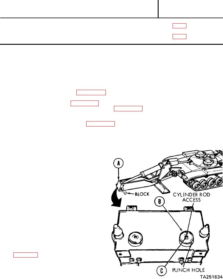
Place wooden block under tongue (A)
1.
and lower tongue (A) (TM 5-5420-202-10).
NOTE
It maybe necessary to hit plug (B) with sledge
hammer to loosen plug (B).
Using punch in hole of plug (B),
2.
unscrew plug (B) while holding
cylinder rod (C) from turning
with screwdriver.
Remove plug (B) from tongue (A).
3.
Relieve hydraulic pressure
4.
Go on to Sheet 2

