
TM 5-5420-228-24
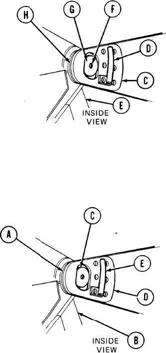
BOOM-OUTRIGGER ASSEMBLY REPLACEMENT (Sheet 2 of 3)
2.
Remove four pin retainers (C) and two
brackets (D). -
Attach lifting device and sling to boom-
3.
outrigger assembly (E).
4.
Have technician operating lifting device raise
sling to take up slack.
5.
Using 7/16 inch socket, remove four grease fittings (F).
Using hammer and drive pin, tap out
6.
two pins (G).
While two technicians guide boom-outrigger assembly (E), have technician operating
7.
lifting device slowly lift boom-outrigger assembly (E).
8.
Move boom-outrigger assembly (E) to desired location and remove lifting device.
Remove lifting device and sling.
9."
Using hammer and drive pin, drive out six bushings (H).
10.
INSTALLATION:
1.
Position six bushings (A) in boom-outrigger assembly (B).
2.
Using hammer and wooden block, drive in six bushings (A).
3.
Attach sling and lifting device to boom-
outrigger assembly (B).
While two technicians guide boom-outrigger assembly (B), use lifting device to move
4.
boom-outrigger assembly (B) into position on vehicle.
5.
Using hammer and drift pin, drive two pins (C) into position.
Place four pin retainers (D) and two support brackets (E) on vehicle.
6.
Go on to Sheet 3
TA251672
4-21

