
TM 5-5420-228-24
HYDRAULIC PUMP REPLACEMENT (Sheet 1 of 3)
TOOLS: 7/16 in. open end wrench
15 in. adjustable wrench
Ratchet with 1/2 in. drive
7/8 in. open end wrench
12 in. adjustable wrench
1-1/8 in. open end wrench
1-1/2 in. open end wrench
3/4 in. socket with 1/2 in. drive
1-3/4 in. open end wrench
Vise
Drip pans (suitable containers)
SUPPLIES:
Pencil (Item 22, Appendix D)
Pipe tape (Item 19, Appendix D)
Protective caps and plugs
Lockwashers (8 required)
Rags (Item 12, Appendix D)
Masking tape (Item 18, Appendix D)
Drain hydraulic reservoir (page 3-74)
PRELIMINARY PROCEDURES:
Remove clutch assembly (page 4-33)
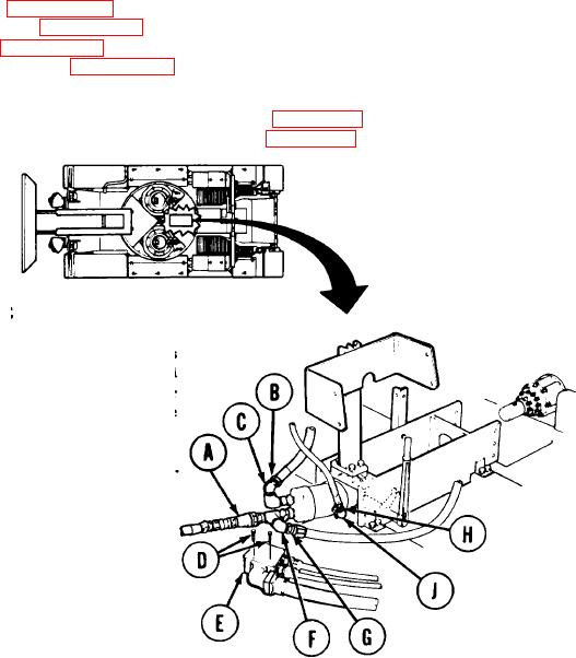
REMOVAL:
NOTE
U s e rags and drip pans to' catch excess
U s e masking tape and
h y d r a u l i c fluid.
pencil to tag lines for installation. Cap or
p l u g all lines and fittings as they are
disconnected.
Manually disconnect hose assembly "CW" (A).
1.
Using 15 inch adjustable wrench, remove
2.
hose assembly "CZ" (B) from fitting (C).
Using 7/16 inch wrench, remove two screws
3.
(D).
Move box (E) aside.
4.
Using adjustable wrench to hold elbow (F),
5.
use 1-1/2 inch wrench to remove hose
assembly "BA" (G).
6.
Using 7/8 inch wrench, remove hose
assembly "CV5" (H) from elbow (J).
Go on to Sheet 2
TA251680

