
TM 5-5420-228-24
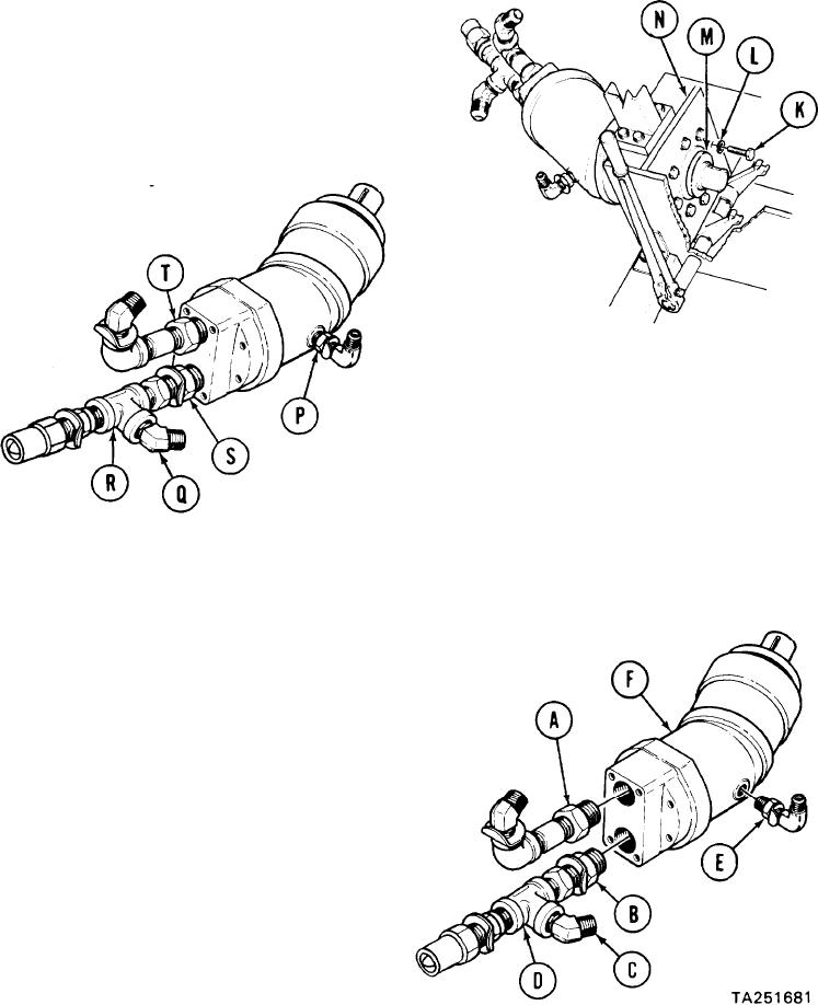
HYDRAULIC PUMP REPLACEMENT (Sheet 2 of 3)
7.
Using socket, remove eight screws (K) and
lockwashers (L) securing-pump (M) to
support (N). Throw lockwashers (L) away.
Remove pump (M) from vehicle and place in
8.
a vise.
Using 1-1/8 inch wrench, remove bushing (P)
9.
and attached parts.
10.
Using 12 inch adjustable wrench, remove
elbow (Q) from tee (R).
Using 1-3/4 inch wrench, remove bushing (S)
11.
and attached parts.
12.
Using 15 inch adjustable wrench, remove
bushing (T) and attached parts.
INSTALLATION:
NOTE
Remove caps and plugs as necessary during installation. Before
installation, use pipe tape on all male threads. Start tape on second
thread so tape will not enter hydraulic system.
Using 15 inch adjustable wrench, install
1.
bushing (A) with attached parts.
Tighten and aline parts to position
shown.
2.
Using
1-3/4 inch wrench,
install
bushing (B) with attached parts.
Tighten and aline parts to position
shown.
3.
Using 12 inch adjustable wrench, install
elbow (C) in tee (D).
4.
Using 1-1/8 inch wrench, install bushing E)
(E) with attached parts. Tighten and
aline parts to position shown.
Place pump (F) in position in vehicle.
5.
Go on to Sheet 3

