
TM 5-5420-228-24
CLUTCH ASSEMBLY REPLACEMENT AND REPAIR (Sheet 6 of 9)
Inspect parts for worn teeth, distortion,
stripped threads, and indications of wear.
3.
Replace all worn or damaged parts.
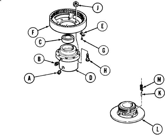
ASSEMBLY:
1.
Using 3/8 inch screw key, install setscrew (A).
2.
Using 7/16 inch wrench, install lubrication fitting (B).
3.
Using arbor press, install bearing (C) into hub (D).
4.
Place nameplate (E) in position on flange (F).
5.
Using hammer, install two new drive screws (G).
6.
Place flange (F) in position on hub (D).
7.
Manually install eight screws (H) and nuts (J).
8.
Using 9/16 inch wrench to hold screws (H), use 9/16 inch socket
to tighten nuts (J).
Using hammer, install six pins (K) in hub and backplate (L).
9.
10.
Manually install six springs (M) on pins (K).
TA251689
Go on to Sheet 7

