
TM 5-5420-228-24
HYDRAULIC PUMP REPAIR (Sheet 10 of 11)
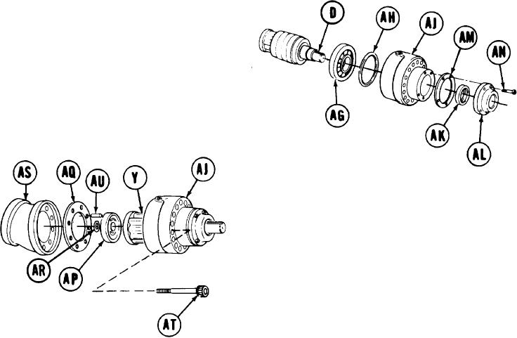
Supporting drive shaft (D) and attached
23.
parts so parts do not separate, carefully
install bearing (AG), ring (AH), and bearing
housing (AJ).
24.
Using arbor press, press new oil seal (AK)
into retainer (AL) with lip facing inside.
Supporting drive shaft (D) and attached parts,
25.
install new gasket (AM) and retainer (AL).
Using 3/16 inch screw key, install four screws (AN).
26.
Have second technician lift bearing housing
27.
(AJ) with attached parts and hold vertical.
NOTE
Install valve plate (AP) as noted
during disassembly.
Place valve plate (AP) on cylinder block (Y).
28.
Place new gasket (AQ) and new
29.
preformed packing (AR) in position.
Place subdeck housing (AS) over assembled parts and onto bearing housing (AJ).
30.
Aline screw holes and scribe marks on subdeck housing (AS) and bearing housing (AJ).
31.
Using 5/16 inch screw key, loosely install eight screws (AT).
32.
Manually install alinement pin (AU) into valve plate (AP).
33.
TA251701
G O on to Sheet 11
4-51

