
TM 5-5420-228-24
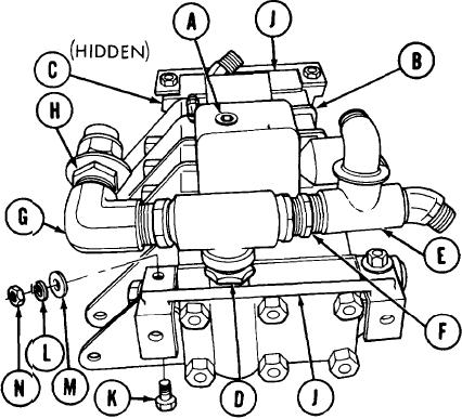
VALVE BANK ASSEMBLY AND BRACKETS REPLACEMENT (Sheet 10 of 17)
INSTALLATION:
NOTE
Remove caps and plugs as necessary during
installation.
Before installation use pipe
tape on all male threads. Start pipe tape
on second thread so that tape will not enter
hydraulic system.
1.
Using 3/8 inch screw key, install
pipe plug (A) into valve bank (B).
2.
Using 1/4 inch screw key, install
pipe plug (C) into valve bank (B).
3.
Using 1-3/8 inch wrench, install
adapter (D) and attached parts
into valve bank (B).
4.
Using adjustable wrench, install
tee (E) and attached parts on
adapter (F).
5.
Using adjustable wrench, install
elbow (G).
Using 1-3/8 inch wrench, install adapter (H) and attached parts on elbow (G).
6.
7.
Position two brackets (J) on valve bank (B), one on each end.
8.
Using 5/8 inch wrench on four screws (K), use 3/4 inch wrench to install
lockwashers (L), flat washers (M), and nuts (N).
Go on to Sheet 11
TA251711

