
TM-5-5420-279-10
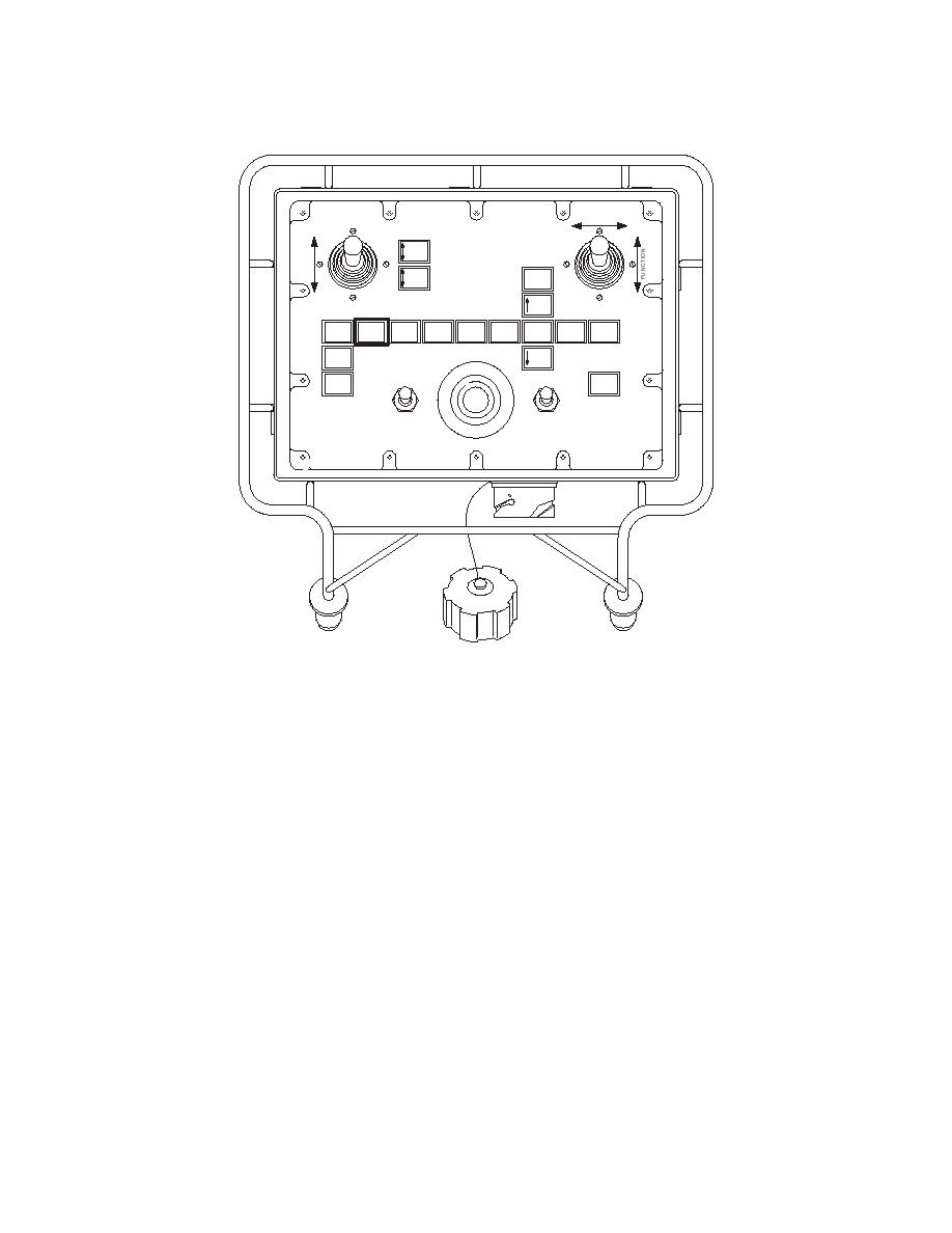
FUNCTION
SELECT
TILT
ROLLER
CARRIAGE
STOW
EMPTY
HIGH
BANK
BEAM
A FRAME
FARBANK
MODE
BEAM
STOW
=LEVEK
L
TOP
BRIDGE
DRIVE
RAISE
SEAT
SELECT
ANGLE
ARTIC
BAN
WINCH
LIFT
LOW
EMERGENCY STOP
POWER
BANK
ROLLER
BRIGHT
OFF
FAULT
BRAKE
OFF
ON
DIM
OFF
ROLLER BRAKE
PUSH TO STOP - TWIST TO RESET
686A356b
Beam Drive Caption
CAUTION
Take care not to overshoot the beam maximum forward position or damage may occur.
The travel stop provided is for emergency use only.
4.7.2.21
Release the joystick when the rear jaws of the last launch beam connected still
protrude 5.5 in (140 mm) from the rear of the launch frame and the lever arm has
dropped into position. Make sure the launch beam slows and then stops in this
position.
NOTE
The launch beam is now correctly positioned to receive the next launch beam module.
4.7.2.22
Repeat steps 4.7.2.10 through 4.7.2.21 until all the launch beam modules are
connected and the launch beam spans the gap. A total of 4 beams should be added
for a 20 m (65.61 ft) bridge and 7 for a 40 m (131.23 ft) bridge.
WARNING
CRUSH HAZARD. FAILURE TO INSTALL THE FINAL LOCKING PIN AND ITS R CLIPS WILL
CAUSE THE LAUNCH BEAM TO FLEX AND CREEP BACKWARDS. FAILURE TO HEED
THIS INSTRUCTION COULD RESULT IN SEVERE PERSONAL INJURY.

