
TM-5-5420-279-10
4.9.2.18
Align the ramp module with the guide on the end beam and slowly lower the ramp
module until the two are fully engaged.
4.9.2.19
Insert the end beam connecting pins and secure them by twisting to lock.
4.9.2.20
Disconnect the bridge module lifter from the position 2 lifting points on the far bank
ramp module.
4.9.2.21
Operate the lift and traverse controls on the crane and position the bridge module
lifter for attachment to the far bank approach ramps and frames on flatrack T1.
4.9.2.22
Remove the end beam wrenches and stow.
4.9.2.23
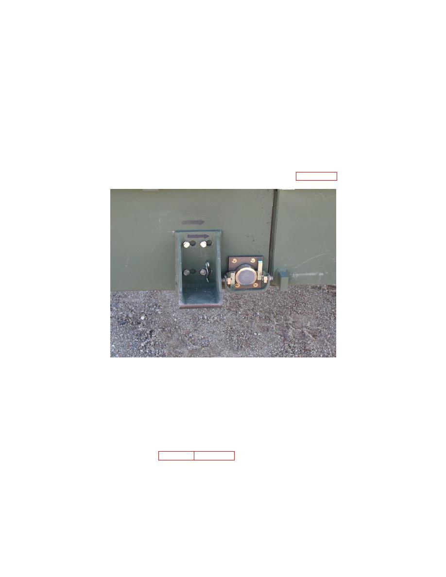
Add ramp lead in brackets to ramp module ensuring that the arrows on the ramp and
bracket point in the same direction, secure with R clips (See Figure 4.14).
CAUTION
To prevent damage to the lifting slings it is important that care is exercised when
connecting the slings to the crane hook. Ensure that the sling is fitted correctly and does
not become trapped by the hook safety clip.
4.9.2.24
Connect the bridge module lifter to the lifting ring of the top pair of approach ramp
frames (far bank approach ramps) ensuring all frame-to-frame hooks are correctly
engaged, refer to Chapter 3 Para 3.9.11 Approach Ramp Transport Frame.
4.9.2.25
Attach tag lines to upper frame strap lugs.
4.9.2.26
Operate the lift and traverse controls on the crane, and using the tag lines to control
the load, lower the far bank approach ramp frame into position, to the left of the
approach ramp module centerline at the marked position, ensuring that the location
lugs on the bottom of the frame sit between the deck units.
4-56

