
TM-5-5420-279-10
NOTE
If pins will not insert correctly check the stabilizer legs of the crane are still level adjust if
necessary.
4.9.4.31
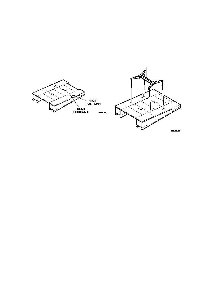
Disconnect the bridge module lifter from the position 2 lifting points on the home bank
ramp module and attach it to the position 1 slinging points. This will compensate for
the change in the center of gravity caused by the connection of the end beam to the
home bank ramp module.
Bridge Module Lifter in POSITION 1 of Ramp Module
WARNING
CRUSH HAZARD. DEATH OR PERSONAL INJURY CAN RESULT IN THE EVENT OF A
SUSPENDED LOAD FALLING FROM THE CRANE. DO NOT STAND CLOSE TO LOADS
SUSPENDED FROM THE CRANE.
4.9.4.32
Operate the lift controls on the crane and raise the ramp module ensuring slings are
vertical prior to lifting.
4.9.4.33
Operate the lift controls on the crane and, using the tag lines, guide the home bank
ramp module into position at the rear of the last parallel module deployed.
4.9.4.34
On the tail lift pendant, press and hold the LIFT UP switch.
Make sure the lift
hydraulic cylinders extend and raise the tail lift platform.
4-76

