
TM 5-5420-280-10
OPERATOR INSTRUCTIONS
RAPIDLY EMPLACED BRIDGE (REB)
NSN 5420-01-481-3959 P/N 12480471
COMMON BRIDGE TRANSPORTER (CBT)
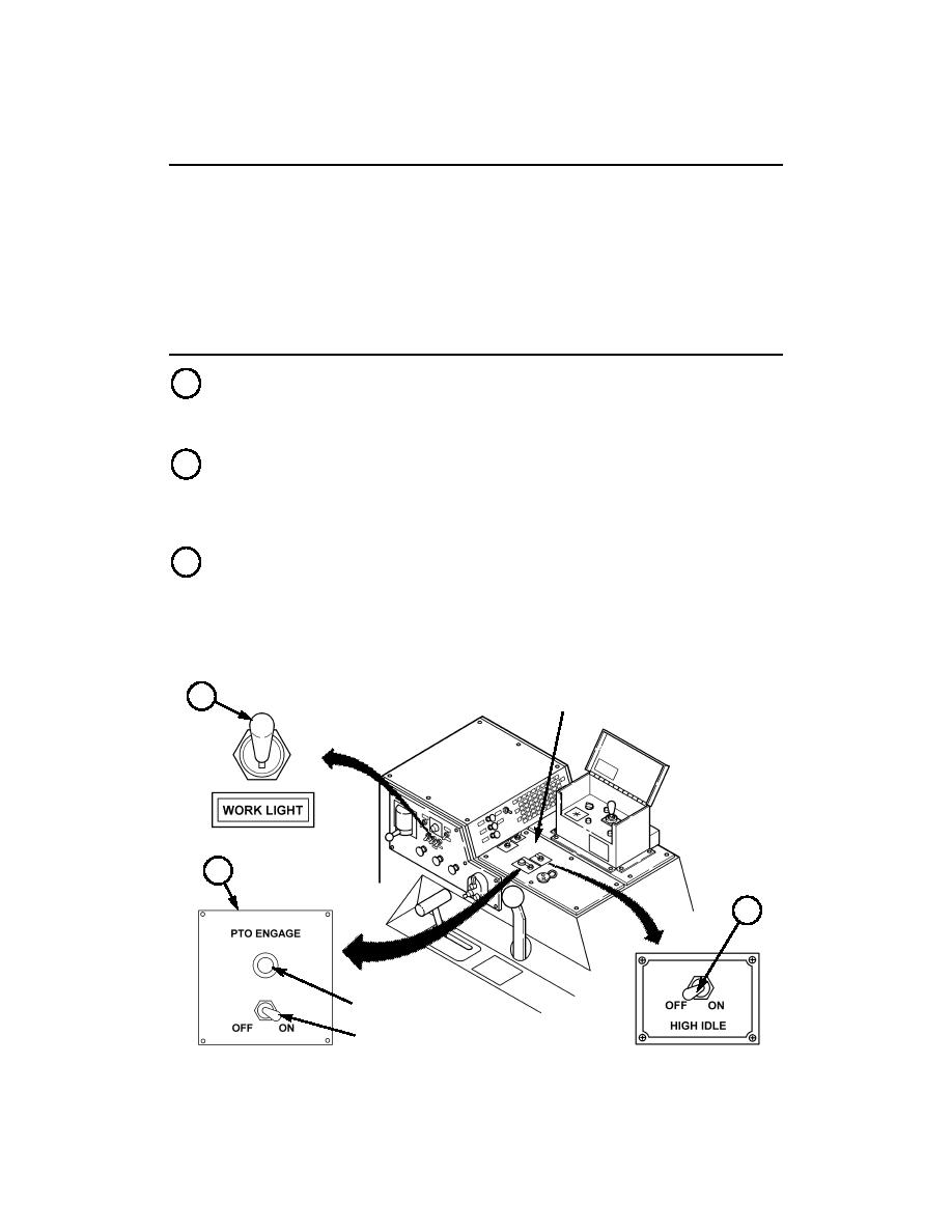
LOAD HANDLING SYSTEM (LHS) CONTROLS AND INDICATORS
A
WORK LIGHT SWITCH -- There is a WORK LIGHT switch located on side
panel to the right of DOMELIGHT switch. Placing WORKLIGHT switch in
UP position turns on the work light at the LHS main frame and hand-held
spotlight at control valve cabinet.
B
HIGH IDLE SWITCH -- There is a HIGH IDLE switch on top panel of cab
console (heater compartment), adjacent to PTO ENGAGE switch and
indicator. The HIGH IDLE switch is placed in the ON position after PTO is
engaged to increase engine idle speed to 1,200 rpm; this is necessary to raise
pump hydraulic pressure for LHS operation.
C
PTO ENGAGE SWITCH AND INDICATOR -- There is a PTO switch and
indicator located on the top panels of cab console (heater compartment)
adjacent to HIGH IDLE switch. Prior to operation of LHS, HIGH IDLE switch
is left in OFF position with vehicle engine running, and PTO is engaged by
moving this switch to ON position. The PTO ENGAGE INDICATOR will light
when PTO ENGAGE switch is in ON position.
CAB CONSOLE TOP PANELS
A
(HEATER COMPARTMENT)
~
C
B
PTO ENGAGE INDICATOR
PTO ENGAGE SWITCH

