
TM 5-5420-280-10
0012 00
SITE REQUIREMENTS AND LAYOUTS (Contd)
e. Construction Site.
Ensure the area can accommodate a normal construction site of 20 ft
(6.1 m) in width by 42 ft (12.8 m) in length to edge of gap. Deployment is
possible on more restricted sites but construction times are increased.
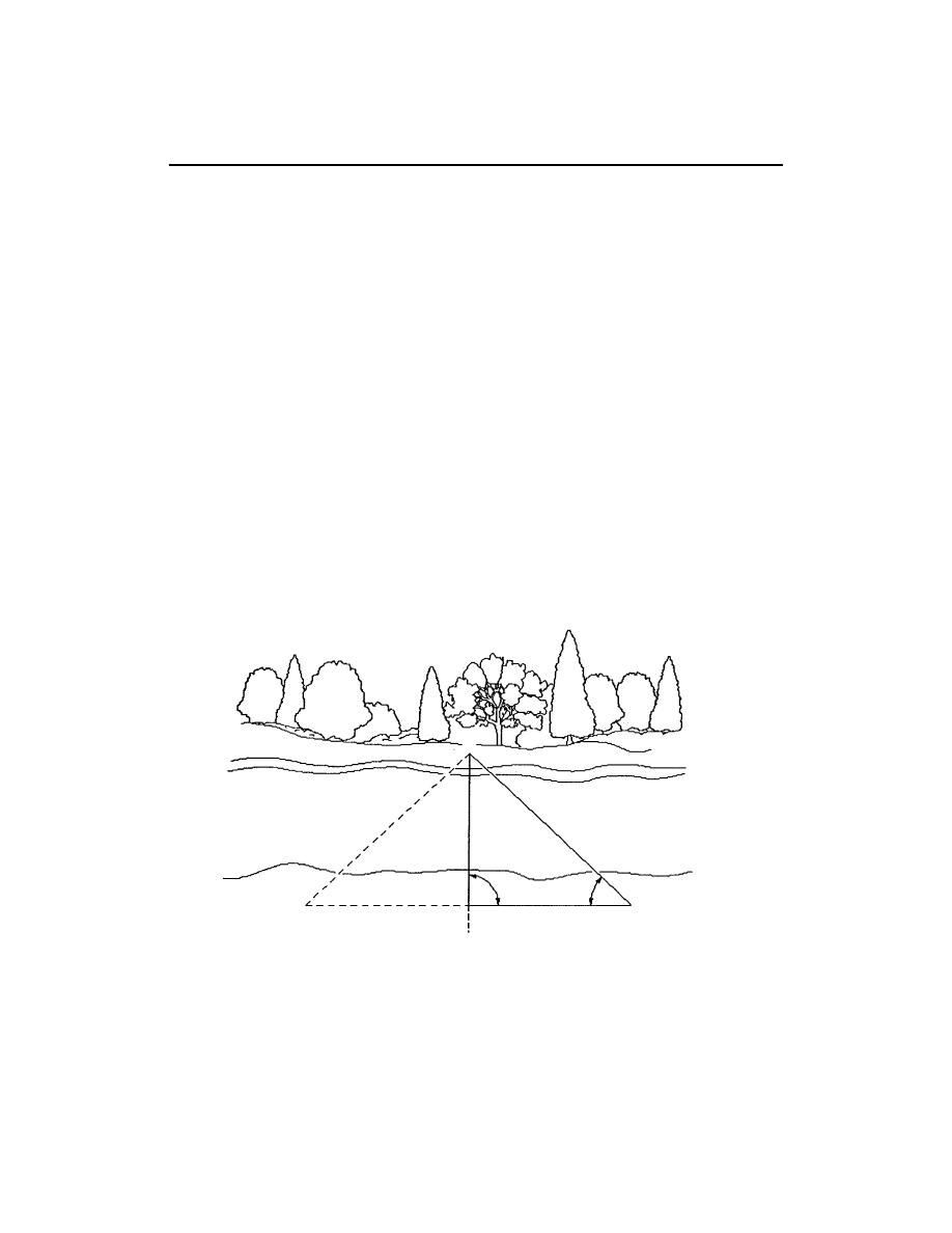
f. Span Measurement.
Stand at a point on the near shore (point A) of the proposed bridge
centerline (refer to figure 5), and select an object (point B) on the far shore
(also positioned on the centerline).
Use a compass and record the bearing of the selected object (point B) along
the proposed bridge centerline (the azimuth). Move up or down the near
shore on a line at a right angle (90 degrees) to the azimuth until a point C
is reached where the bearing of the selected object (point B) equals the
azimuth bearing plus or minus 45 degrees.
Use a tape to measure the distance between points A and C along the near
shore (which equals the distance between points A and B the gap) to
determine the gap dimension.
B
45
90
C
C
A
PROPOSED BRIDGE CENTERLINE
Figure 5. Span Measurement.
0012 00-7

