
TM 5-5420-280-23&P
0002 00
EQUIPMENT DESCRIPTION (Contd)
BRIDGE EQUIPMENT FEATURES (Contd)
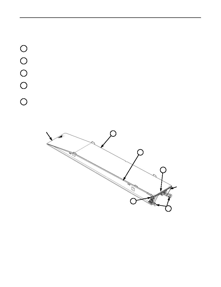
K
BRIDGE QUARTER A U-shaped structure having a ramp end, coupling end, and flat deck plate
running the length of its top surface.
L
GUARD RAIL A 2-in. (50-mm) high railing welded to the inside edge of deck plate on each bridge
quarter that serves to guide vehicles to center when crossing bridge.
M
CROSSFORCE COUPLING BUMPER The steel insert bolted to connecting end of each bridge
quarter that functions to align and prevent the coupled bridge assembly from twisting at its center.
N
to coupling end of each bridge quarter that function to hold the two bridge halves together at the
bottom. Help levers are manually operated during launch and retrieval.
O
UPPER COUPLING The lock mechanism, located on coupling end of each left bridge quarter, that
functions to hold the two bridge halves together at crossforce coupling bumpers until bridge
assembly is emplaced.
RAMP END
K
L
M
COUPLING
END
O
N
BRIDGE QUARTER, LEFT-HAND SHOWN
0002 00-27

