
TM 5-5420-280-23&P
0074 00
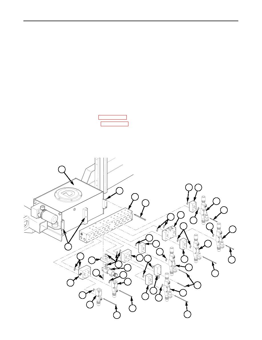
HYDRAULIC CONTROL VALVE MANIFOLDS REPLACEMENT (Contd)
INSTALLATION (Contd)
NOTE
Apply a light coat of hydraulic oil to O-rings at installation.
Install manifold adapters and control valves as noted in removal.
2.
Install eighty new O-rings (16), and manifold adapters (17), (21), (22), (25), and (27), control
valves (18) and (24), and flow control valve (23) on manifold (7) with screws (19), (20) and (26) and
tighten screws (19), (20), and (26) evenly to 44 lb-in. (5 Nm).
3.
Install new O-rings (5) and (6) and plug (4) on end of manifold (7).
4.
Install new O-rings (3) and (8) and fittings (2) and (9) on manifold (7).
5.
Install steel tube (11) on adapter (9) and tighten nut (10).
6.
Connect elbow (12) on adapter (2) and tighten nut (1).
7.
Install hydraulic lines. Refer to WP 0071 00.
8.
Fill hydraulic reservoir. Refer to WP 0016 00.
NOTE
The pallet hydraulic system is self-bleeding, and with exception of
the telescopic tube hydraulic cylinders, there is no requirement for
bleeding air from the system.
9.
Operate hydraulic system and check for leaks. Refer to TM 5-5420-280-10.
13
~
16 17
14
7
18
15
19
21
16
16
16
16
18
16
18
17
14
16
16
22 16
17
19
25
16
18
24
26
20
16
24
27
19
23
18
16
17
16
24
19
20
19
0074 00-3

