TM 5-5420-280-23&P
0092 00
BEARING SHAFT MANIFOLD REPLACEMENT (Contd)
INSTALLATION (Contd)
4.
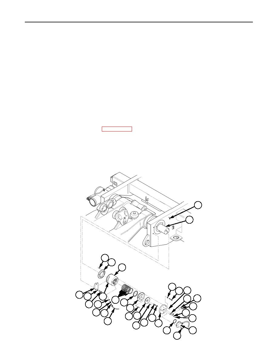
Install manifold (5) on bearing shaft (2).
5.
Install retaining bracket (32) on pallet (1) and slot (29) on manifold (5) with washers (31) and
screws (30).
6.
If removed, install potentiometer drive screw (19) on cover (21) with nut (18).
7.
Install cover (21) on bearing shaft (2) with three screws (20).
8.
Install four new O-rings (28) and adapters (27) on manifold (5).
9.
Connect four steel tubes (25) with new tube seals (26) to adapters (27).
10.
Install potentiometer adapter plate (17) on two dowel pins (8) and manifold (5) with three
washers (6) and screws (7).
11.
Install potentiometer (9) and ground wire (10) on adapter plate (17) with two washers (12) and
screws (13). Do not tighten screws (13).
12.
Adjust potentiometer. Refer to WP 0093 00.
13.
Install cover (14) on potentiometer adapter plate (17) with new O-ring (16) and four screws (15).
NOTE
The pallet hydraulic system is self-bleeding, and with the exception
of the telescopic tube hydraulic cylinders, there is no requirement
for bleeding air from the system
14.
Operate hydraulic system and check for leaks. Refer to TM 5-5420-280-10.
1
2
3
4
5
6
8
7
32 31
29
10
9
24
23
30 28
11
22
27 26
12
3 21
18
13
25
19
17
20
14
16
15
END OF WORK PACKAGE
0092 00-3/4 blank


