TM 5-1940-277-34
VALVE AND SPRING ASSEMBLY REPLACEMENT INSTRUCTIONS
(Continued)
LOCATION
ITEM
ACTION
REMARKS
i.
Valve and
Tap threaded
Use non-metallic
spring assem-
shaft that held
hammer.
bly (14)
shift lever and
pull valve out
of case through
valve cover
opening.
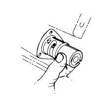
INSTALLATION
2.
Transmission (1)
a.
Valve and
With threaded
Valve should
spring assem-
end first place
only require
bly (14)
valve assembly
hand pressure
into hole on
to fit into
right rear of
case.
transmission.
Push valve in
until it "bottoms"
against the
shoulder in
case bore.
b.
Valve and
Aline the slot in
spring assem-
control valve with
bly (14)
the bottom bolt
hole for the valve
cover.
2-331