
TM 5-5420-202-20-1
LOCATION AND DESCRIPTION OF INTERNAL COMPONENTS (1 of 2)
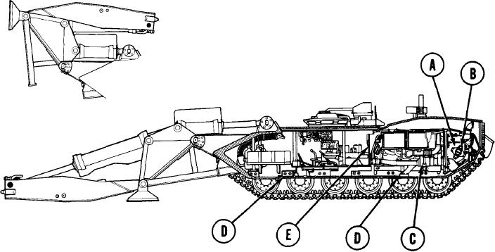
TRANSMISSION
(A)
Transmits engine power to the final drives to move the vehicle. The transmission has
two forward ranges, low and high, and one reverse range.
UNIVERSAL JOINT
(B)
Transmits power from transmission to final drives. There is one universal joint on each
side of the transmission.
ENGINE WITH POWER TAKEOFF
(C)
Provides power to move vehicle. Provides power to drive hydraulic pump.
HULL DRAIN VALVES
(D)
Provides means for draining any water accumulated.
ENGINE AIR CLEANER INTAKE
(E)
Provides means of drawing air from crew compartment for air cleaners. This is usually
done during fording or during operation under dusty or sandy conditions.
LAUNCHER IN
TRAVEL POSITION
TA249770
1-4