
TM 5-5420-202-20-1
SYSTEMS OPERATION - Continued
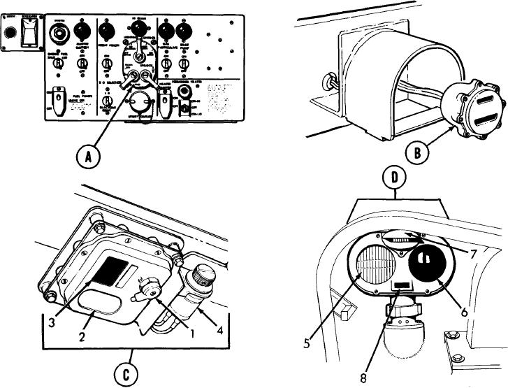
LIGHTING SYSTEM. Vehicle lighting consists of headlights and taillights that are controlled by
the LIGHTING CONTROL switch on the MASTER CONTROL PANEL. Headlight assemblies
have service drive and infrared-filtered blackout lamps and marker lamps. Service drive and
s t o p lamps are in left taillight and blackout lamps are in both right and left taillights.
D o m e l i g h t is controlled by a three-position switch to select white or red light and turn
domelight off.
LIGHTING CONTROL (MASTER CONTROL PANEL)
(A)
TAILLIGHT-STOPLIGHT-BLACKOUT LIGHT ASSEMBLY
(B)
DOMELIGHT
(C)
1.
THREE-POSITION SWITCH
2.
WHITE LIGHT
3.
RED LIGHT
4.
DOMELIGHT RESISTOR
HEADLIGHT ASSEMBLY
(D)
5.
SERVICE DRIVE LAMP
6.
INFRARED LIGHT
BLACKOUT DRIVE
7.
TA249787
BLACKOUT MARKER
8.
2-17