
TM 5-5420-202-20-1
SYSTEMS OPERATION - Continued
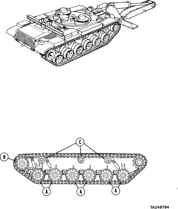
TRACKS AND SUSPENSION SYSTEM. Major components of the track and suspension system
are described below.
ROADWHEELS AND SUSPENSION. Twelve roadwheels, dual-mounted on six hubs, carry
(A)
vehicle weight on upper s u r f a c e o f l o w e r t r a c k s p a n .
Space between dual-mounted
w h e e l s is running channel for track alining centerguides.
R o a d w h e e l arms 1, 2,
and 6 bear shock absorber mounts. Each arm is sprung with torsion bars.
(B)
COMPENSATING IDLER WHEELS. Identical to and interchangeable with roadwheels,
s e r v e s as track alining channel for centerguides a n d maintains track tension by
m e a n s of track adjusting link connected to roadwheel number one and idler arm
w h i c h forces i d l e r w h e e l f o r w a r d o r r e a r w a r d t o m a i n t a i n c o n s t a n t t e n s i o n o n
unloaded free portion of track.
TRACK SUPPORT ROLLERS. Three dual-mounted track support rollers on each side of
(C)
vehicle support upper track span between sprockets on drive hub and compensating idler
wheels. One track support roller also drives the speedometer.
(A)
ROADWHEELS
(B)
COMPENSATING IDLER WHEELS
TRACK SUPPORT ROLLERS
(C)
2-24