
TM 5-5420-226-20-3
BRAKES ADJUSTMENT (Sheet 4 of 8)
CAUTION
Make sure brakes are fully released before making brake
adjustment. Failure to fully release brakes can cause
internal damage to cross-drive transmission.
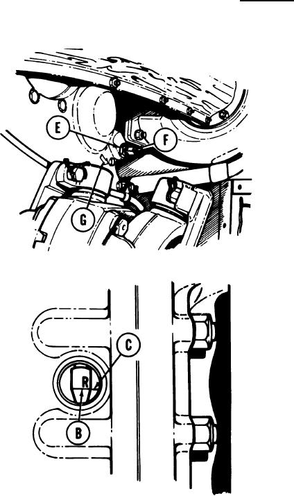
6.
Using 7/16 inch wrench, turn brake adjusting
worm (F) about 25 turns in opposite direction
of arrow (G) on transmission end cover (right
side, turn clockwise; left side, turn
counterclockwise).
7.
Using 7/16 inch wrench, attempt to line up
index line (B) marked R with index mark (C)
by turning brake adjustment worm (F) in
direction of arrow (G) on transmission end
cover (right side, turn counterclockwise; left
side, turn clockwise).
If index line (B) marked R, and index
8.
mark (C) are lined up, using 7/16 inch
wrench, hold brake adjusting worm (F).
Using 15/16 inch wrench, tighten locknut
(E).
NOTE
If index line (B) marked R, and index mark (C) are not
lined up, notify supervisor that brakes require higher
level maintenance.
Go on to Sheet 5
TA169205
13-81