
TM 5-5420-227-24
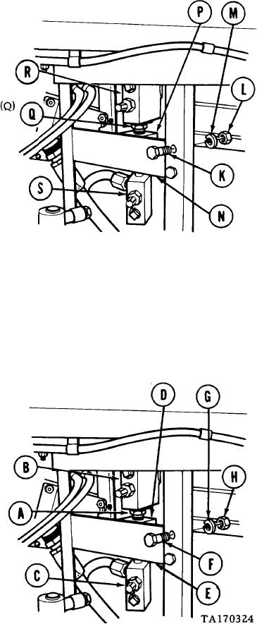
SEQUENCE AND LOCKING CYLINDER RELIEF VALVE (RV5 AND RV6) REPLACEMENT
(sheet 2 of 3)
6.
Holding screws (K) with 3/4 inch wrench, use socket
to remove four nuts (L) and lockwashers (M). Throw
lockwashers (M) away.
7.
Remove four screws (K) and bracket (N) with
manifold (P) attached.
8.
Using 1-1/8 inch wrench, remove two nipples
with relief valves "RV6" (R) and "RV5" (S)
from manifold (P).
Using vise to secure two relief valves (R)
9.
and (S), use 1-1/8 inch wrench to remove two
nipples (Q) from relief valves (R) and (S).
INSTALLATION:
NOTE
Before installation, use pipe tape on all male threads.
Start tape on second thread so tape will not enter
hydraulic system.
1.
Using 1-1/8 inch wrench, install two nipples
(A) in relief valves "RV6 (B) and "RV5"
(c).
2.
Using 1-1/8 inch wrench, install two nipples
(A) with relief valves (B) and (C) in
manifold (D).
Place bracket (E) with manifold (D)
3.
attached in position in vehicle.
4.
Manually install four screws (F), new lock-
washers (G), and nuts (H).
5.
Holding screws (F) with 3/4 inch wrench,
use socket to tighten four nuts (H).
Go on to Sheet 3
3-98