
TM 5-5420-228-24
VALVE BANK ASSEMBLY AND BRACKETS REPLACEMENT (Sheet 11 of 17)
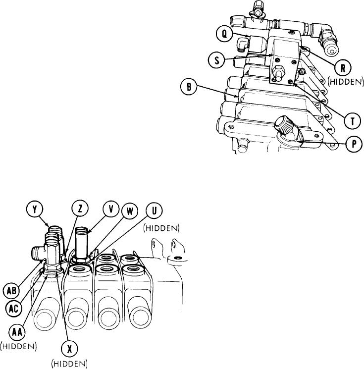
Using adjustable wrench, install
9.
and aline collar "CW" and elbow (P).
Using pipe wrench, install and
10.
aline adapter and attached elbow
(Q).
preformed
new
install
11.
Manually
packings (R) in relief valve (S).
Using 5/16 inch screw key, install
12.
four screws (T) securing relief
valve (S) to valve bank (B).
13.
Manually install new preformed packing
(U) on tee (V).
Manually install and aline tee (V).
14.
15.
Using adjustable wrench to hold tee (V), use 1-1/4 inch wrench to tighten jamnut (W).
Manually install new preformed packing
16.
(X) on tee (Y).
Manually install and aline tee (Y).
17.
18.
Using adjustable wrench to hold
tee (Y), use 1-1/4 inch wrench to
tighten jamnut (Z).
19.
Manually install new preformed packing
(AA) on tee (AB).
20.
Manually install and aline tee (AB).
Using adjustable wrench to hold tee
21.
(AB), use 1-1/4 inch wrench to tighten
jamnut (AC).
TA251712
Go on to Sheet 12
4-63