TM 5-5420-278-10
0035 00
0035 00-18
BRIDGE ANCHORAGE (Contd)
TOWER DESIGN
When installing an overhead cable system, Class 60 towers are used to ensure
that the master cable remains at least 3 ft (0.9 m) above the water level. The tower
components are provided with each set of M4T6 and Class 60 and located in the
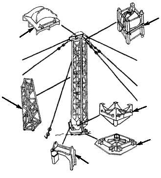
Ribbon Bridge Supplemental Set. The tower assembly is made up of a tower base, a
pivot unit, six tower sections, a tower cap, a cap adapter, and two wire rope slings.
(Refer to figure 13.) If Class 60 towers are not available, Bailey bridge panels can be
used to construct an adequate tower. For additional information, see Appendix B in
TC 5-210.
CAP
CAP ADAPTER
PIVOT UNIT
BASE PLATE
ERECTION ARM
CAP + BASE = 3 FT 8 1/4 IN. (1.13 M)
SECTIONS = 10 FT 10 IN. (3.30 M) EACH
MAXIMUM HEIGHT = 68 FT 8 1/4 IN.
(20.95 M)
TOWER SECTION
EXAMPLE
Given the following reconnaissance data,
design the tower for an overhead cable
system used to anchor the IRB:
River width: 600 ft (183 m)
Current velocity: 7 feet/sec
(2.1 meters/sec)
Bank heights:
Near shore: 10 ft (3 m)
Far shore: 3 ft (0.9 m)
SOLUTION
1. Determine the required tower heights.
Near shore: HR = 3 + S – BH =
3 + 15.2 – 10 = 8.2 ft (2.5 m)
Far shore: HR = 3 + S – BH =
3 + 15.2 – 3 = 15.2 ft (4.6 m)
2. Refer to table 8 to determine actual
near and far shore tower heights.
Near shore: H = 14 ft 6 1/4 in.
(4.43 m)
Far shore: H = 25 ft 4 1/4 in. (7.73 m)


