TM-5-5420-279-10
19 Rotate the A-frame legs, by pressing A-frame rotate DEPLOY button on the
interface panel until the DEPLOYED light illuminates.
20 Insert the A-frame rotate shootbolts.
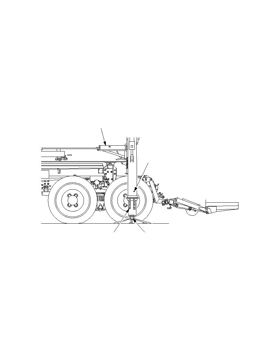
21 Position the stabilizer feet under the stabilizer legs.
22 Remove the stabilizer leg pins and R clips.
23 Lower the stabilizer legs onto the feet.
NOTE
Only just rest the feet on the ground DO NOT start to lift the A-frame.
24 Refit the stabilizer feet by fitting the securing U-bolt and new nyloc nuts.
1, 6
22, 32, 33
23
21, 22, 24
686A662
25 Release the twist locks on both sides, raise the stabilizer legs to pin hole No.
eleven. Replace the pins and clips.
26 Drive the launch vehicle forward to extend the launch frame.
27 Plug the launcher chest pack in, and remove the shootbolts on the relax
mechanism.
28 Go to position 4 on 4 position rotary switch in the vehicle cab.
29 Go to BEAM ANGLE on the chest pack. Operate the right hand joystick to
exercise the articulator cylinders up and down to check for correct operation.
30 Insert the shootbolts on the relax mechanism and unplug the chest pack.
31 Turn the rotary switch to position 3, reverse vehicle to close slide frame.
11-64


