
TM 5-5420-280-23&P
0002 00
EQUIPMENT DESCRIPTION (Contd)
BRIDGE EQUIPMENT FEATURES (Contd)
Q
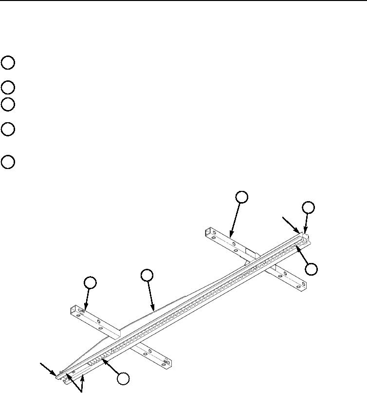
SUPPORT TUBES The two square tubes welded perpendicular to launch beam that support and
permit bridge quarters to slide outward to roadway width and inward to transport width.
R
LAUNCH BEAM The center support structure of a bridge half.
S
BEAM A hat-shaped steel support that contains roller contact surfaces and drive pins that
interface with pallet launcher.
T
DRIVE PINS There is a channel, bolted to bottom of launch beam, that contains 84 round pins
and functions to engage bridge half with pallet pin wheel drive gears to move bridge on pallet during
launch and retrieval.
U
RAIL TRACK There is a hardened steel rail track bolted to ramp end of launch beam that
functions to engage bridge with pallet pin wheel drive gears to move bridge onto pallet at retrieval.
Q
S
COUPLING
END
T
R
Q
RAMP
END
U
ROLLER CONTACT
SURFACES
LAUNCH BEAM, BOTTOM VIEW
END OF WORK PACKAGE
0002 00-29/30 blank
Change 1